Some of you might remember me from years ago. I have not been in the forums for the past few years. But I have been improving my machining skills. I decided to give machining a yoyo another try. I currently have access to a Haas Mini Mill 2 and that is what I am using. Next year I should have access to a cnc lathe, but until them I thought I would see what I can do.
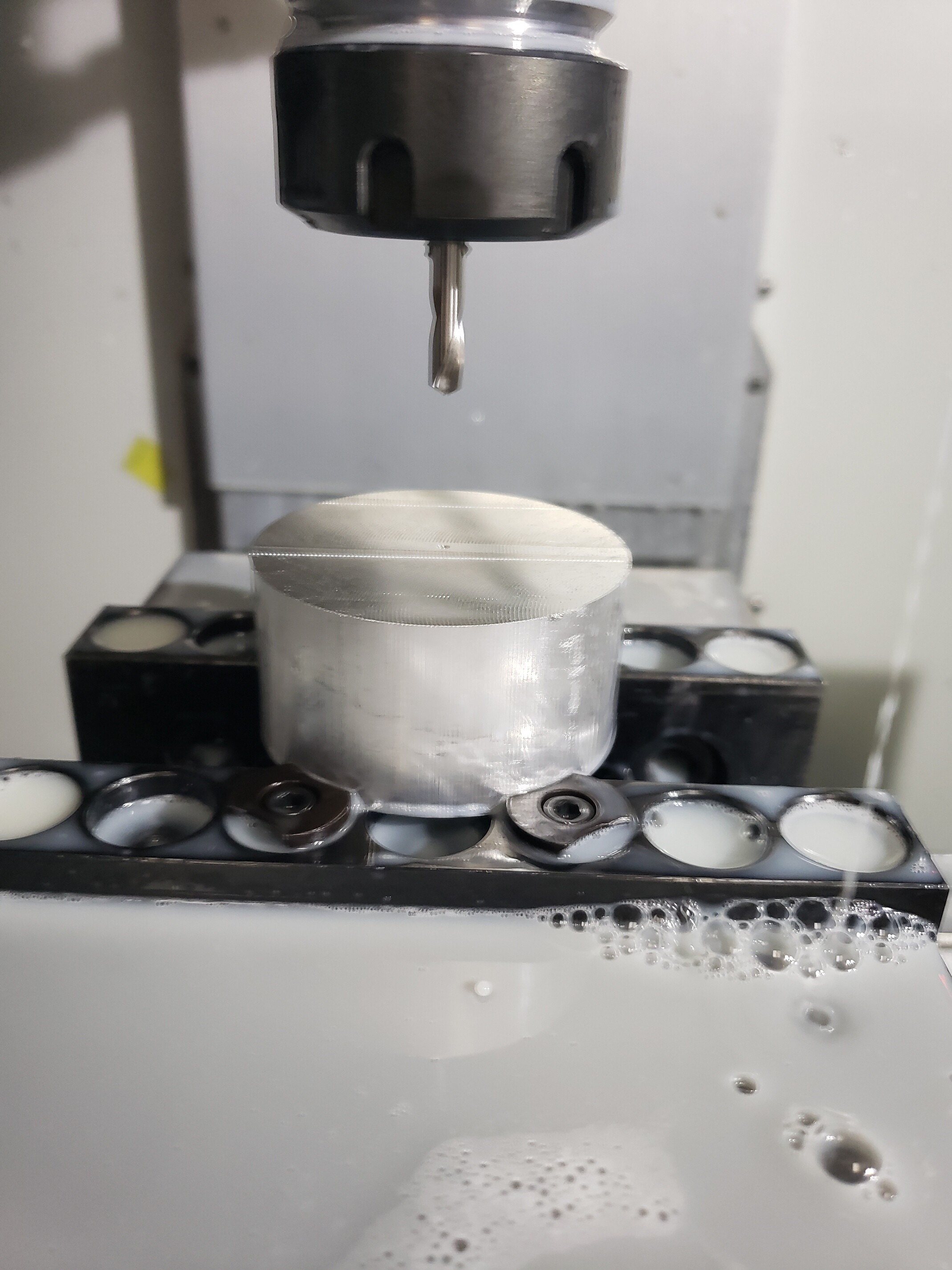
Step 1: Start with a cylinder of aluminum 2.25 inch in diameter
This was just a test part so I didnt machine the bearing seat or the response. I am waiting on a smaller tool to arrive to make those easily. I also didn’t thread the hole yet. I really wanted to see how the surface would turn out. I have a few changes to try but for a first attempt it turned out pretty good.
Very cool! I come from a family of machinist so i love to see this stuff. Very interesting to see you go after it on a mill. Please keep these posts coming!
I spend a couple hours improving my machining process a little. I got a endmill which is the right size to machine the bearing seat and the response groove. The cnc mill can drill and tap the axle hole, machine the bearing seat and response groove perfectly. The curved surface is much harder. I modified my code to make this surface come out with less scallops. It definately turned out much better. The surfaces that ad more that a 45 degree angle look and feel great. I only have one area where there are still some ridges. this is due to that surface being close to flat.
I have not tapped the holes on these two test parts yet. I could do it by hand right now using a thread cutting tap. But I plan to use the CNC to do it with a thread forming tap instead. This is better because it pushed the metal to form the thread instead of cutting it away. The threads are stronger, but more importantly on blind holes that have threads very close to the bottom they are better. Thread cutting taps create shavings of metal which fall to the bottom of the hole. So once the forming tap arrives i will add that step.
Right now this machining step takes about 20 minutes. But I know that is very conservative. I think I can cut that in half without too much work. But honestly since I am not trying to do a production run and since I can let it run unattended the cycle time is not a big concern. I also have a second set of the work holders which will let me put two cylinders of metal into the vice and machine 2 hubs with one program.
How do you clamp it down for machining the other side? I can see the clamp marks in the endstock, but that obviously won’t work if you can’t damage the already machined bits.
You are correct that I can not use the same fixture method. I have 3 ideas for how to do this.
Machine a fixture which has matching geometry for the bearing seat and response and use a screw to hold them together. This is my favorite option because it should work for any yoyo with the same bearing seat / response groove. It should let me make several different yoyo prototypes using the same fixture. The downside is that this fixture would not be strong enough.
Machine a fixture that has the mating geometry for the bearing seat and the response groove, but also has matching material to support the hub. This would be much stronger, but I would need to make a new fixture for each yoyo design.
Do the whole thing in reverse and machine the other side of the hub and some of the rim, then machine custom clamps to hold it to machine the other side. This is the most work per / yoyo design
There are a lot of mounting options. Can you like the ancient summit documentary? I remember seeing someone machine yoyos on a cnc mill before and it would be nice to watch it again and see if my experience lets me understand more from the video.
Thanks for linking the video. I had seen that one before. It was not the one I was remembering though. I know someone had a video where they machined a yoyo on a cnc mill instead of a lathe.
You are right that it is called an expanding collet. I dont happen to have one of those right now, but I probably could get one. They expand to make a larger cylinder. So if your hub has a nice cylinder section you can hold it with those. But if the hub does not, you would need to machine one to have a matching curvature. Additionally, those are often opened and closed with compressed air, so you have to have a controller to do it. They do have some that work by tightening a screw though. I dont happen to have one of those, and they dont work on every design either. They also take some work to make sure the yoyo is centered on them perfectly.
I am going to try my method out first and see if it works. My goal is not production speeds or quantities. Instead I am trying to develop a method to produce very low quantities of a big mixture of yoyos. I want to get the method down where I can product 1-5 yoyos of a design quickly and without custom tools, or fixtures. This included programming the cnc, loading the material, machining it, flipping and machining the back, them tumbling and blasting.
Interestingly my the my company will be getting is the same brand as the one in the video but the size bigger and will have dual spindles. So kinda like 2 lathes in one.
After a few tries, I am happy with this surface finish. I wanted the surface to be good enough to play straight out of the machine. While I still plan to glass bead blast the hubs, it smooth the surface very much.
After doing a fair bit if research, a few hours of changing settings, simulating, and a few tool changes I now have a very smooth surface.
I also programmed a few tweaks to the bearing seat and programmed the treading of the axle hole. I am using a forming tap which is supposed to make stronger threads. It also is better suited to blind holes because there are not chips of metal. I have to check the thread tomorrow and I think I can program it deeper too. I want to get the maximum thread engagement I can because I will be using this hole to hold the hub while I machine the other side.
Yeah, it does look cool. But the surface is very smooth. I think if it was sandblasted you wouldn’t be able to see any surface defects. I also plan to do some tests with vibratory tumblers and polishing.
I made some more progress on this project. Having a full time job and family life means I can only carve out a few hours a week to work on this project. This week my goal was to build the fixture to hold the hub upside down for the second machining operation. I am not sure if my idea will work, but I am willing to give it a try.
I used a left over piece of 17-4 stainless steel to machine this.
It is 0.75 inch tall, and 6 inches long. The width is a little under 1.5 inches. The sides and bottom are machined very flat and it fits in my 6" vice easily. It has two holes for a #6 screw to pass through. The top has 0.25" counter bore for the center axle of the yoyo to fit into. It also has a matching ring machine the sits into the response groove on the hub. When you tighten down the screw it pulls it all together and the locking geometry should provide a pretty secure connection.
It is designed to hold two hubs at one time and fit into my 6 inch vice. I made it from 17-4 stainless so that it would be stronger than the hubs. That way the fixture will not wear out after a lot of uses. It is quite heavy.
My goal with this project is to develop a method for making a lot of various type of yoyos. I know a lot of people have ideas and designs they want to prototype. Obviously the methods I am using are not the way production yoyos are made. All the yoyo designs will need to have the same bearing size and response groove. But I should be able to machine any shape of the hub.
Next step is to program the reverse machining. I know I wont be able to do any heavy machining in this setup. But I also don’t think I need to.