For more performance oriented designs, I’ve seen MOI go around 33k-35k for both halves. So for each half around 16.5k-17.5k for each half.
However, a lot of these designs were 56mm in diameter and were around the 65-66g range.
1-2mm decrease in diameter doesn’t seem like a lot but it does make a noticeable difference in moi value.
Of course moi doesn’t have to be that high to make a yoyo spin long during regular play. The response area and how the shape is actually influences the spintime more than just a 5-10% increase in moi. I’ve had designs with way less moi spin longer than those with much higher moi thanks to them being designed with everything in mind.
Visualize yourself of the shape you’re making and how the string would rub along the side of the yoyo when you’re making it. The smaller the contact area, the less friction it will have against the string.
The prototypes I recently got has around 14-15k moi for each half, with 54.5mm diameter and 42.5mm width at 65.9g weight, and I think they spin for a remarkably long time. They’re not a super rimweighted design either since they were a capped design.
I bet you can get moi much higher with your current specs and same shape. It’s all about maximizing the amount of material you have with subtle design elements that would minimize the spinloss occurring from string rub.
Try picking up a set of calipers and taking some measurements of yoyo’s and bearings in your collection. Really helps with the visualization and CAD process. Looks like you’ve taken a great first step and I’m excited to see what you come up with!
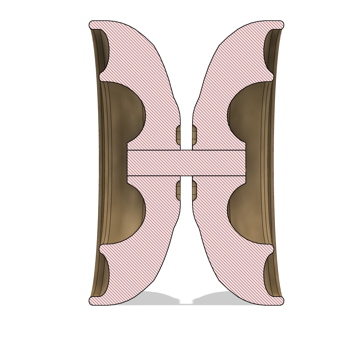
@BearingGoBRRR thank you for sharing your first design! Your bearing seat looks visually correct; the dimensions also look about right. However, I would add a bit pf space between the virtual “center line” of the yoyo and the bearing post; to give it clearance when it closes all the way.
This part of the design is very concerning to me! It is ultra sharp! For the outer corners I usually start with a pretty large radius; 1.5mm or so. Depending on design goals that could go up or down, but it’s a safe starting point that won’t get you in trouble by hurting your hand or cutting someone.
I don’t have calipers and I didn’t know that’s what “those measuring things everyone used in yoyo videos” were called, but I definitely want to get one now. Also, I forgot to round the corners, I’ll be sure to do that since it does look kind of dangerous. Thank you guys for the tips and advice, I had a lot of fun designing the yoyo and can’t wait to get started on either updating this design or making a new one entirely.
Hi there, i need help with my CAD model. I am making a yoyo on TinkerCAD and I am looking for help. Please give me any advice on the model and I also need an axle 10mm axle model. Thanks. 3D design project_nitrogen/crash_002 - Tinkercad
Fusion 360 offers a free for personal use version which may be a better option for CAD. Allows you to import models for the entire McMaster-Carr catalogue, which would help with you issue finding a 10mm axle model. Just food for thought, and the prototype you’re making looks awesome! Cheers
You can drop in a ~4mm diameter 10mm long cylinder to block out the axle location and check for things like the cup not being in too close to the axle. Just as a quick option while modeling.
For your design, it has lots of pointy edges that you should dress up with fillets (probably 1.5mm radius for the outermost edge, smaller is fine for other corners).
You haven’t put in every measurement, so it’s a little difficult to tell, but its close.
You will need to put a chamfer or a radius on the edge of the bearing post to help put in the bearing without causing damage.
The little lip the bearing sea sits on is quite wide too. This probably won’t interfere at all, but I would go no larger that 1mm. That probably just a preference though.
I suggest putting a .1mm fillet on all of those sharp little corners.
You have made the pad recess 1.3mm This will be fine, but they will be ever so slightly recessed by about .1mm.
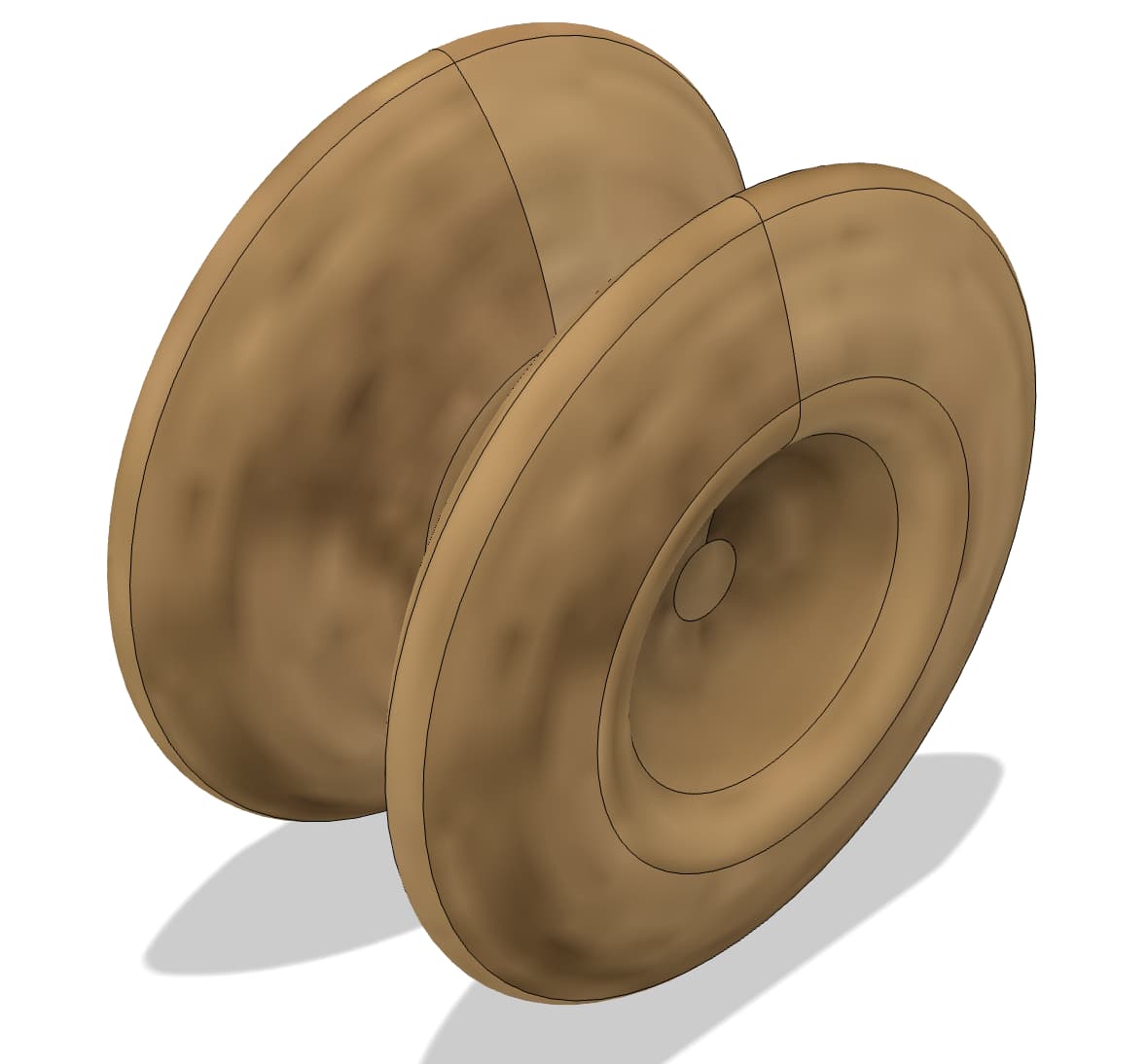
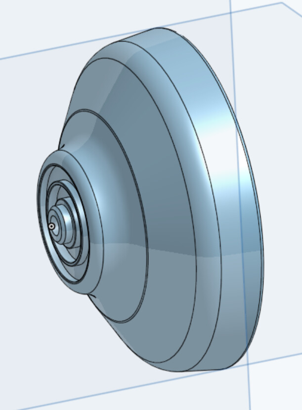
I’m trying to make a Spotlight Ultra copy but one that has a fingerspin hub and is a little wider but I’m not sure if this is any good. How it would play, and my program says it is 29 grams??? Any thoughts, tips or helpful criticism?
Not a designer, but it looks great. Seems like 29g is in the ballpark if that’s just the weight of the half. What’s the overall weight you’re aiming for? How much does a bearing weigh?
[edit] So if a bearing is ~2g, I’m not sure if that’s normally included in the specification weight, but hope this helped at all, though I’m guessing you already thought of all this.