


No ideas yet, but the idea of you homespinning something up with Spinworthy is a cool one. My jam.
My ideas do tend to be horrible to turn though. A local military facility couldn’t even spin up a working flying Lemon.![]()
No ideas yet, but the idea of you homespinning something up with Spinworthy is a cool one. My jam.
My ideas do tend to be horrible to turn though. A local military facility couldn’t even spin up a working flying Lemon.![]()
I love a challenge. Feel free to toss weird stuff at me. It’s always fun to look at oddball stuff.
Taking a look, that design doesn’t seem too crazy to me? What was the issue?
They had difficulty turning the bearing seat and lip cleanly. The bearing didnt spin when installed. A tooling issue. I figured it was going to be easy for thwm to make but I was wrong. I couldnt even enter the facility to help them troubleshoot it. Its off limits to civilians.
I’ll be honest my experience with military US, UK and AU is that the equipment may be military grade but that just means lowest bidder. I’m not surprised if they had troubles vs a more specialized shop…
Definitely one of the more… interesting tolerance bands for sure. It gave me some trouble when I was cutting the first designs. I also often have to make minor tweaks to the designs clients send me to make them fit my tools and be sure everything works right.
I typically think of it as “minimum standard” more than “lowest bidder,” but I deal with mil-spec and the resulting military grade stuff more for process and finish requirements than anything.
Personally I think any shop should be able to interpret and meet job tolerances pretty well, no matter what they do normally … One thing I have noticed is that a lot of designers aren’t sure how to identify or communicate certain tolerances. It’s not a bad thing, necessarily, it’s just a skill that’s specific to certain industries that a lot of people don’t think about. I’m sure I’ll get around to making a post about it at some point ![]()
Someone once told me that nobody should have access to military grade firearms. I responded: “Oh, mine are much better than military grade”.
Its pretty easy to communicate. Just make sure the CAD export you send them is dead accurate. All they need to do is turn it exactly as it is.
I mean always a good guideline. One thing I notice is that some people will include all design features in their base drawings and some will rely on modeled features for stuff like filets and chamfers. When I get sent a DXF, it’s important that all expected features exist inside it. I usually ask for a solid model as a backup just in case so I can double check.
Unfortunately this is functionally impossible. Even a CNC machine isn’t 100% accurate. For example my bearing posts generally wander inside of a roughly 0.001in window, ±0.0005in from the theoretical perfect defined in the program. There’s not really anything I can do about that variance, it just kinda is, you know? Different machines will have different levels of repeatable precision.
Obviously that doesn’t excuse a shop for not having brains between ears when it comes to understanding the kinematic endpoint of the design, but it’s a factor. Benefit of actually having experience cutting yoyos is that I know what the tolerances should be and where to aim my cuts to have things come out working right.
I’ll write this up better at some point, but to a certain extent the design itself has to account for machine error. The designer should also make clear to the fabricator what sort of boundary conditions exist. The closer you get with your stipulations to ±0 from the design, the higher the price goes and the harder it is to find someone to cut your stuff.
This is absolutely true, though. I do my best and I’m told my communication is pretty good ![]()
Yep the big thing is for the shop to communicate the machining tolerances. No machine can get perfect dimensional accuracy and usually the design needs to accommodate a certain amount of tolerance difference to be successful.
3d printing is similar. Sure I can calibrate the machine get it damn near perfect but there are so many variables I can’t manage that can impact the outcome and result in a slightly different outcome.
I’m curious why a dxf if those are usually 2d. Do you normally take just the profile dxf? Is that because it’s being turned so you don’t need the 3d you need to know where to cut on a known diameter circle?
I’m curious because I’ve got an idea stuck in my brain that is going to take machined plastic and I’m used to 3d printing only, doing some research.
Kinda depends. I use 3D solids alongside the DXFs. I can work with either one, but the DXF is a good standard to get. On a base level, all the 3D models I work with are based on DXF-like sketches anyway. If I get a solid model, I’m creating a sketch slice to get it back into a 2D sketch for analysis anyway.
Of course when I’m doing the designing they’re a bit… messier. Solidworks defines shapes by using dimension and parametric callouts, and when there’s a ton of them it gets hard to parse without zooming in right to where the dimension was placed ![]()
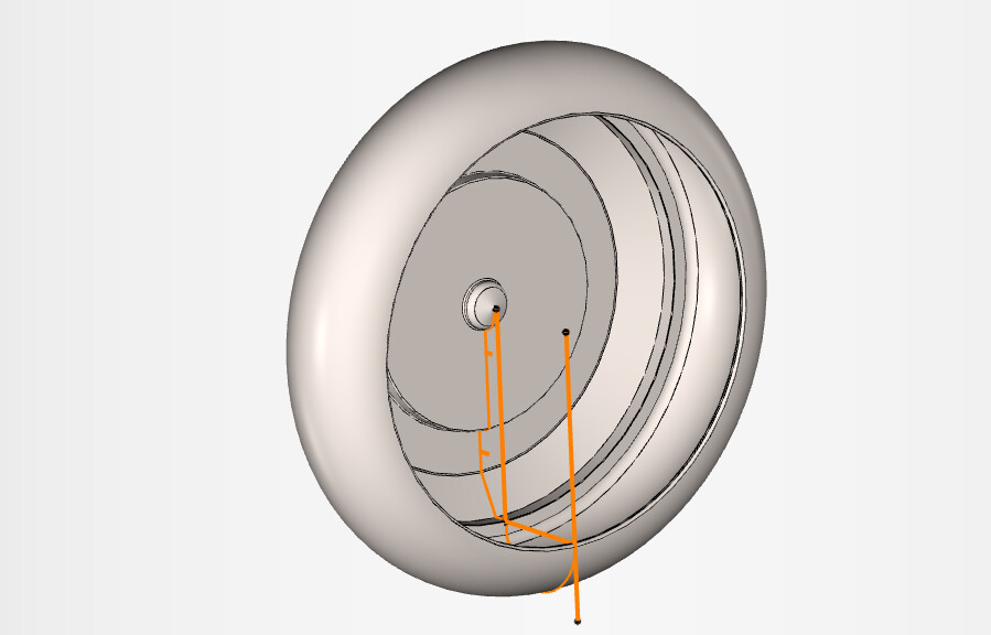
After I pull the solid into Esprit, I also import an altered version of the base sketch in the form of a DXF. A lot of the tools used for more automated feature creation don’t give me certain features I want to see for building tool paths. For example, these two lines that kinda turns the cup into simple cylinder are used to define the profile for the tool that roughs out the cup itself. It can’t get into the undercut and it doesn’t have the geometry to make any sort of feature below a flat face.
You’ll also see odd tails and things that look slightly out of place, which are likewise used to give myself feature geometry that wouldn’t exist otherwise. The only downside to using a DXF is that it often doesn’t show features included after the generation of the solid form. So like using solid modeling features to generate things like chamfers and fillets.
You can see what that looks like overlayed on top of the 3D model here
Everything highlighted in blue is a feature recognized and defined for the purpose of creating toolpaths.
Toolpaths can look kinda messy, too. Red lines are feed lines, meaning a dictated rate of movement, typically measured in feed/rev (remember the encoder issue?) and the green dashed lines are “rapids,” where the machine is just told “move as fast as you can.”
Thank you! Very informative
Any time! I love questions like these.
It looks like I should get serious about profile design and actually draw some if I’m going to send a design out to a machine shop. I usually look at fusion 360 like digital clay and just use like chamfer, extrude, shell, etc to manipulate a shape into the yoyo I want. I’ve done one or two profile revolved into a shape designs but by and large I ignore all the actual cad in my cad software lol.
At least with the tools available to me that’s not an impediment. If you can get me a .STEP file, I can create a dxf on the fly pretty easy. I’d be happy to spit them out for you if you ever wanted.
I should also point out that for the large majority of turning work pieces I don’t really need a dxf. I’ll sketch bespoke geometry if and when it’s needed. I’ve just noticed that yoyos tend to need a lot more handholding ¯_(ツ)_/¯
This is literally me.
Actually thinking a little harder on this, some of your profiles wouldn’t really suit a DXF anyway. Anything not circular or that has milled features is gonna require a solid model or at least DXF’s of every possible view/machining setup.
Oh I was just talking about communication.
The burden to turn it exactly as the file is the machinist’s department.
I’m pretty good at that part of things XD
Feel free to reach out in DM’s if you want me to look over anything!